
|
|
|

Back to basics
Part 6 - Valve gear layout
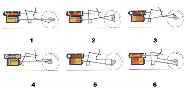
Position the mouse cursor over part of the image below to find its name and function
The function of the locomotive valve gear is to regulate the movement of the valves so that steam is admitted and exhausted from the cylinders in relation to the position of the pistons. It also allows the driver to alter the length of steam admission, known as cut-off, and to reverse the locomotive. Copyright © by John Daniel 2013.
The valve spindle is pulled back to the end of its motion as the radius rod is drawn by the oscillating expansion link. This admits fresh steam to the rear of the piston and exhausts the steam from the front of the piston through its port
As the radius rod is pulled back by the expansion link, the combination lever and valve spindle is pushed forward and cutting off the admission of steam to the back of the piston
The combination lever continues to push the valve spindle forward and begins to open the rear port and exhaust the steam from behind the piston
The piston begins to move backwards although the valve spindle is continues forwards, and opens the port to the front of the piston and admitting a fresh charge of steam to that area
The rearwards moving combination lever regulated by the advancing radius rod, pulls back the valve spindle and cutting off the admission of steam to the front of the piston
The combination lever continues to travel back and in doing so uncovers the front port
In the Walschaert valve gear, which was common among many railway companies except for the Great Western, fore-and-aft movement of the valve spindle is controlled by both the combination lever and the expansion link. These two sources of fore-and-aft motion are joined at the point where the combination lever and radius rod are pinned together.
The movement of the expansion link is obtained from an eccentric rod attached via the crank axle. Adjustment to the length of valve travel is made by raising or lowering the position of the radius rod within the expansion link. This is achieved by operation of the reversing rod from in the cab. The length of travel of the radius rod, and therefore of the valve spindle, depends on the rod's position within the expansion link. Maximum valve travel giving maximum steam admission is obtained when the radius rod is positioned furthest from the centre of the expansion link. Moving the radius rod from one half of the expansion link to the other, reverses the movement of the locomotive by admitting steam into what otherwise would have been the exhausting side of the piston's cycle.