|
|
|

Back to basics
Part 2 - Locomotive tender design
Position the mouse cursor over part of the image below to find its name and function
The locomotive tender carries enough fuel and water to supply the trains needs between fuel and water points. Until the start of the 20th century, a weight of five tons of coal and 3500 gallons of water was sufficient for most of Britain's railways, however with the introduction of long non-stop runs and a higher rate of steam production from higher powered engines, tenders capacities were increased up to 10 tons of coal and 6000 gallons of water. Copyright © by John Daniel 2013.
Footplate of the locomotive
Drawbar between the locomotive and tender
Injector - supplies water to the boiler
Water feed pipes linked to the locomotive and tender
Steam brake cylinder - some tenders were fitted with these to assist the locomotive brakes
Tender doors - for the removal of coal from the tender
Coal space - with a capacity up to ten tons
Water space - with a capacity to carry up to 6000 gallons
Brake gear
Water pick-up scoop - to collect water from troughs while in motion
Pick-up standpipe
Pick-up dome - water from the standpipe hits the dome and falls into the tender water space
Air vent - so that air is expelled from the water space when the tender is filled
Water filler - to fill the tender from shed and platform water points
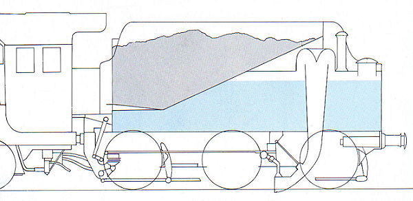
The water tank was originally of a horseshoe shape with the coal piled onto a flat floor in the centre, but later the design was altered to that as shown above. The inclination at the rear of the coal space encouraged the coal to slide forward onto the low horizontal section called the 'shovel plate'.
Baffles were fitted inside the water tank to stabilize the water while the locomotive was in motion, while at the rear, a water filler topped by a heavy hinged lid gave access to water cranes at stations and depots.
With the exception of the Southern Railway, most main-line locomotive tenders were fitted with a water scoop to collect water from lineside troughs. Generous air vents were required due to the rush of water as was a dome shaped deflector at the top of the water space.
Tenders were only detached from the locomotive at times of heavy repair and so the coupling between the two was made much stronger than normal couplings used. The London and North Western Railway used timber-framed tenders into the 20th century. The idea was that this would absorb any collision damage and so protect the locomotive; a sort of early crumple-zone.
The main limitation on tender sizes was the length available on turntables and because of this, some large locomotives were fitted with small tenders. At the other extreme, Sir Nigel Gresley designed some exceptionally large tenders for the non-stop London to Edinburgh service, carrying 5000 gallons of water and eight tons of coal.
Mechanical stokers, successfully used in North America, were considered a little unnecessary for Britain's railways where the firing rate was well with the capacity of the fireman. Trials with the mechanical stokers were performed on four engines though: on three class 9F's and a Southern Merchant Navy, but unless the coal was of pitiful quality, they were considered a bit of a luxury.