|
|
|

Back to basics
Part 4 - Firebox layout
Position the mouse cursor over part of the image below to find its name and function
The firebox of a steam locomotive is designed to burn fuel efficiently and produce adequate heat to boil water and so create steam. The firebox must be of a size to burn enough fuel for the heaviest duty without forcing unburnt fuel off the firebed. Copyright © by John Daniel 2013.
Inner firebox crown plate - the top of the inner firebox and the bottom mounting point for the crown stays
Inner firebox crown plate - the top of the inner firebox and the bottom mounting point for the crown stays
Inner firebox crown plate - the top of the inner firebox and the bottom mounting point for the crown stays
Fusible plugs - melt and extinguish fire if water level is low
Fusible plugs - melt and extinguish fire if water level is low
Outer firebox wrapper plate
Crown stays - suspend the inner firebox in an envelope of water
Tube plate - acts as a mounting for the various tubes of the boiler
Brick arch
Deflector plate - guides the air from the firehole towards the fire
Firehole and door
Outer firebox
Cast iron firebars
Inner firebox
Ashpan and dampers
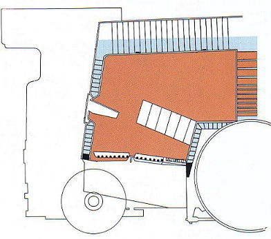
Firebox widths vary from those that overlap the engine frame and wheels to the type that is waisted to fit between the frames. The top of the firebox may round and therefore follow the circular profile of the boiler barrel, or roughly flat known as the Belpaire type. This latter firebox is more costly to produce but it gives more steam space at the top where it needed most.
The firebox consists of an inner and outer shell; the outer firebox is made of steel whereas the inner firebox can be made from steel or copper. The space between the inner and outer fireboxes, usually 3 to 4 inches at the sides but 1˝ to 2 feet at the top, is controlled by over 1000 metal stays that located the inner firebox at steam pressures of around 250 pounds per square inch. The level of water that surrounds the inner firebox is controlled by the injectors that force water from the tender into the boiler, however as a safety feature, if the water level should drop below the inner firebox crown plate, fusible plugs made from a low melting-point alloy, melt and extinguish the fire.
The grate at the base of the inner firebox consists of cast-iron firebars with air spaces between. The amount of air admitted through the grate to the underside of the fire is adjusted by damper doors in the ashpan. Additional air is admitted through the firehole and guided towards the fire by the deflector plate. This ensures complete combustion of the gases within the firebox and eliminating the periods when unburnt fuel is drawn off the firebed and produce unwanted smoke and block the boiler tubes.
Cleaning the grate entailed paddling or lifting the ash directly from the firehole with a long shovel then removing several firebars with heavy tongs and pushing the remaining clinker and ash into the ashpan. To assist in this operation, some locomotives were fitted with a drop section grate, or in later days with a rocking grate that would allow the ash to be shaken from the fire while the locomotive was in use.