
|
|
|

The Severn Railway Tunnel.
Chapter 5 - Methods of Tunnelling.
Now only 130 yards
separated the headings from the English and Welsh sides of the river, but instead of driving the headings towards each other, Walker concentrated on the building of the tunnel proper. This would effectively provide another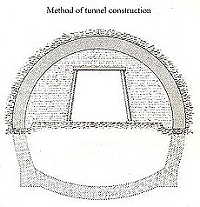 headwall should the headings be threatened by flooding yet again.
The normal method of tunnelling at this time was to drive headings, 7 to 9 feet square in a position close to the bottom of the the finished tunnel and then open out, or break-up as it was known, to the full size of the tunnel by removing material upwards and sideways. In this way all support for the roof would start at the bottom of the heading. After Hawkshaw's decision to lower the tunnel by 15 feet, the original headings were positioned near to the top of the tunnel, which meant material was removed downwards in addition to upwards and sideways. As supporting the tunnel then became more difficult, the method that Walker used was to open out upwards and sideways as normal and then line the break-up with a brick lining. With the top half of the tunnel secure, the bottom of the tunnel could then be excavated downwards followed by the building of an invert brick lining. Due to this method, the work was completed in short sections to maintain adequate support as each section progressed.
The first area opened out was at the bottom of the Sea Wall Shaft in January 1881. This area, of course, had not been affected by the Great Spring. Other sections of finished tunnel were also commenced west of the Sea Wall Shaft, but on the third section, about 600 feet from the shaft, water suddenly burst in from the roof of the break-up. Attempts to seal the leak from below were not successful and to make matters worse, the water leaking into the section was sea water. Between the English Stones and the Gloucestershire coast is a small tidal pool known as The Salmon Pool. At low tide, the depth of water in this pool is about 3 feet, and so Walker sent a number of men onto the estuary around the Salmon Pool to try to find the location of the hole. Unable to find its position by this method, Walker then ordered thirty of his men to hold hands and walk across the pool. In water waist deep, the men walked until one of them suddenly disappeared from view. Rescued by the men either side, this now gave Walker the information that he wanted. To ensure that the hole was not made larger by the water entering into the section, Walker ordered that the pumps at the Sea Wall Shaft be stopped and the water allowed to rise to the level of the tide outside. Meanwhile, large amounts of loose and bagged clay were loaded onto a schooner and at high tide the mixture was placed over the hole. As shown in this example, Walker was right in not completing the headings between the two sides of the river.
Walker then turned his attention to the method of removing the spoil from the works. Originally men were employed to push the skips the full 1ľ miles of the main heading. This was a very expensive and time-consuming procedure. Walker introduced strong ponies to pull the skips and also replaced the rails from the lighter 18 pounds to the yard to the more durable 42 pounds to the yard. In the opened-out tunnels, the rails were carried on decking about 2 feet above the bottom of the tunnel, but in the 7 feet headings, the roof of the heading was increased in height for clearance. Next, a system of sixty electric lights were fixed in the heading from the Old Shaft to the first tunnel section.
As previously mentioned in this chapter, Walker kept the 130 yards of separation between the headings on the English and Welsh sides of the river, however to increase the ventilation in the 1ľ miles heading under the river, the two headings were joined together on the 26th of September 1881. Ventilation was also assisted by the installation of a 18 feet diameter fan above the New Shaft.
For blasting in the works, Walker exclusively used tonite made by the Cotton Powder Company. It was selected as it gave off less noxious fumes than any other explosive other than the highly-washed gun cotton. Tonite was also unaffected by cold or moisture and was conveniently packaged. The method used was to drill into the rock to the required depth and a suitable number of tonite packages was placed into the hole together with a fuse. The number of packages was critical; to few and the process would have to be repeated, too many produced a danger of loosening rock outside of the required area. Lime cartridges were tested as an alternative to tonite as lime had been used in coal mining operations with considerable success. A large bore hole was packed with lime and water pumped into the charge. The resulting chemical reaction caused the lime to swell, generating gas and removing the rock around the bore hole. During on such test, the principal foreman, Joseph Talbot, was watching the water being pumped into the charge of lime, when suddenly the charge blew out and hit Talbot full in the face. For two days, it was feared that he may have lost his sight, but fortunately he made a full recovery. The incident though convinced Walker not to continue using the lime cartridges.
The heading was driven east from the shaft at 5 miles 4 chains to within 26 feet of the Great Spring and then a full-sized tunnel was erected over the same length. In addition, a heading west from this shaft was driven and sections were made into tunnels. In places the rock proved to be hard conglomerate containing large amounts of water that required considerable pumping power.
The production of bricks close to the 5 miles 4 chains shaft was further improved to the point that within half an hour of the shale being removed from the works, the bricks were placed in the drying shed before firing.
On the 2nd of November 1881, Walker received orders from Sir John Hawkshaw to continue with the works as rapidly as possible. Considering that the headings under the river were flooded between October 1879 and January 1881, made Walker proud of his achievements since his arrival at Sudbrook. Therefore in December 1881, in order to accelerate the the work within the tunnel and headings, Walker decided to increase the workforce and bought 4˝ acres of land for various purposes and leased a further 3˝ acres for the building of additional houses.
By the end of 1881, 500 feet of full-sized tunnel together with 1,500 feet of top break-up was completed, although this was only a fraction of the 23,000 feet length of the completed tunnel. In addition, the small village of Sudbrook had grown to include a mission-room for 250 people, a coffee house with a reading room, a saw mill with a carpenter's shop, a stable for twenty horses complete with fitting and blacksmith's shops and a two-storey main office for the works. For the well-being of the men, on the top of each shaft was constructed a cabin for taking meals and changing clothes.
On the Gloucestershire side of the river there was a difficulty in obtaining land except directly over the line of the tunnel. Since the tunnel at this point was constructed with what was thought to be a 6 feet bed of marl over it, brick houses would have prone to subsidence and so timber houses were built here. As proved later, to was to be a wise decision.
Copyright © by John Daniel 2013