
|
|
|

The Severn Railway Tunnel.
Chapter 2 - The Work Begins.
The first work involved in building the tunnel was the sinking of a shaft 15 feet in diameter and 200 feet deep. Originally the shaft was to be located at the edge of the Shoots, but after objections on the grounds that it would be dangerous to shipping, the shaft was begun in the parish of Portskewett on the 22nd of March 1873, half a mile from Sudbrook Farm. Prior to the commencement of the shaft, six cottages and an office were built on a small plot of land bought by the Great Western. A single line of track from Portskewett station to the shaft provided supplies of bricks, timber and other materials, in addition to a winding engine with a lift cage to transport men to the bottom of the shaft and a pumping engine to clear away any water in the workings.
A contract was given to William Dennis and Benjamin Perkins of Bristol for the sinking of the shaft, however by August 1873, the depth of the shaft was just 60 feet as two large springs were met, completely overwhelming the existing pump and so additional pumps were provided. Finally, in December 1874, the shafts had reached its target depth of 200 feet and from this shaft, a heading seven feet square was started eastwards beneath the Shoots.
Initially the headings were created by hand-drilling the rock and blasting, but this only produced about 12 feet of heading per week, even though the men worked day and night on two twelve-hour shifts. In January 1875, air-driven drills were introduced fed by a compressor on the surface. At first, this innovation was not popular with the men, until the time when the compressor suffered a breakdown and the men had to return to hand-drilling for a time. With the addition of these air-drills and the adoption of three eight-hour shifts, work progressed at about 50 feet per day, however as the length of the heading was increased, adequate ventilation for the men seriously reduced. To overcome this, Richardson installed a steam-driven extractor fan over the shaft in May 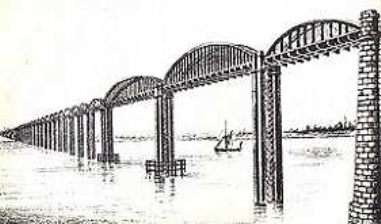 1875.
1875.
The following month, construction of the Severn Bridge at Sharpness began, which replaced the original plans for 'Fowler's Line', was to be 1,400 feet long over twenty-one spans supported by huge cast iron cylinders. Connecting the Great Western lines in South Wales to Midland Railway lines in Gloucestershire, a saving of 30 miles would be made against the route presently in use. However, the Great Western were less than enthusiastic about the scheme, due partly to their commitment to the tunnel and also because of the proposed terms of the Midland Railway's involvement.
By the end of July 1875, about 300 yards of heading under the river had been completed, but the going was getting more difficult. Although the rock itself was sound and hard, there were open joints which produced large amounts of fresh water. To guard against flooding the whole of the heading, Richardson ordered that a wall, 6 feet thick, be built 340 yards from the shaft. A heavy iron door together with a valve fitted in the wall would seal off the heading in the event of a flood, enabling the pumps to bring the situation under control.
After two and a half years work in August 1877, the length of the heading was almost a mile long, but a second shaft had been partly sunk next to the original. This new shaft of 18 feet in diameter, known as the 'Iron Shaft' as it was to be clad internally with iron sheets, was to be used primarily for permanent pumps to drain the tunnel.
At this stage, the directors of the Great Western decided to let the contract for the works and subsequently they received tenders of between Ł987,000 and Ł1,350,000. Richardson was horrified by these amounts, but the contractors pointed out that an undertaking of this magnitude contained so much that remained unknown. Hawkshaw, now Sir John, advised the directors to accept the tender from Thomas Walker. Walker had worked under Hawkshaw on the continuation of Brunel's Thames tunnel under London's docks together with work on the London Underground, however, on Richardson's advice, the directors decided not to let the contract until the heading had been driven for the full length of the tunnel. Fresh tenders would then be invited, eliminating most of the uncertainty surrounding the work, and consequently achieving a more realistic price for the work.
Two small contracts were then made; one with Oliver Norris of New Passage to sink a shaft on the Gloucestershire side of the river, and to drive headings east and west from that shaft, and the other contract was with Roland Brotherhood of Bristol to sink two shafts on the Monmouthshire side, again with headings east and west. The names of the new shafts were given as the Sea Wall Shaft in Gloucestershire and the Marsh Shaft and the Hill Shaft in Monmouthshire. The Great Western would continue to drive the heading under the river, but it agreed that Oliver Norris would drive a second heading from the original or Old Shaft as it was now known, some 40 feet above the first heading. This would provide the necessary 1 in 100 gradient of the tunnel and the shaft end of the bottom heading would become a drainage area.
Work now progressed at a high rate and the little water that was found in the sinking of the additional shafts and headings was easily removed with the pumping power that the works had obtained. Nobody realised, however, that any large amounts of water encountered would come from the land and not from the river overhead; unfortunately disaster was just around the corner.
Copyright © by John Daniel 2013