|
|
|

4900 'Hall' class introduction
Running numbers 4900 to 7929.
For a number of years, the Running Department Copyright © by John Daniel 2013.
Built 1928-30 (4900 - 4980) to lot number 254,
1931 (4981 - 4999, 5900) to lot number 268,
1931 (5901 - 5920) to lot number 275,
1933 (5921 - 5940) to lot number 281,
1935 (5941 - 5950) to lot number 290,
1935-36 (5951 - 5965) to lot number 297,
1937 (5966 - 5975) to lot number 304,
1938 (5976 - 5985) to lot number 311,
1939-40 (5986 - 5995) to lot number 327,
1940 (5996 - 5999, 6900 - 6905) to lot number 333,
1940-41 (6906 - 6915) to lot number 338,
1941-43 (6916 - 6958) to lot number 340,
1944 (6959 - 6970) to lot number 350,
1947-48 (6971 - 6990) to lot number 366,
1948-50 (6991 - 6999, 7900 - 7919) to lot number 368,
1950 (7920 - 7929) to lot number 376.
 of the GWR required a '43xx' type engine with a leading bogie and standard No. 1 boiler. Although the Mogul class were successful, it was felt that a 4-6-0 engine would reduce nosing and provide the ideal all-round locomotive. Such a machine was outlined in Churchward's standardisation plan, although he felt that a ten-wheeled engine would have greater traction if it was to the 2-8-0 configuration, to which he designed the '28xx' class.
When C. B. Collett became Chief Mechanical Engineer in 1922, he was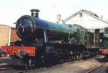 asked to produce a 4-6-0 to replace the Mogul '43xx' class. His answer was to reduce the coupled wheel diameter of 'Saint' class No. 2925 Saint Martin from 6 feet 8˝ inches to 6 feet 0 inches. After a short period of evaluation, the first order for eighty locomotives to these dimensions was given. These first eighty were fitted with spring compensating beams fitted between the axles but subsequent orders did not have them fitted and on the original eighty, the beams were gradually removed. Further locomotives of the class were ordered with very little alteration to the original design. Nos. 6916 to 6970 entered traffic without names during the Second World War but naming of these engines took place between 1946 and 1948.
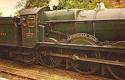 Experiments with electric lighting and mechanical lubricators were performed, the latter fitted as standard from No. 7910 onwards.
A series of modifications to the frames, cylinders and saddle were designed by F. W. Hawksworth when he became Chief Mechanical Engineer and this version of the 'Hall' class is known as the '6959' or 'Modified Hall' class. At the same time, larger three-row superheaters were fitted ( except Nos. 6966 to 6970 ) although with subsequent boiler changes, some members of this class received earlier two-row superheater boilers. Altogether, the 'Hall' and 'Modified Hall' classes numbered 330 locomotives.
The power classification of the class was 5-MT, the G.W.R. power class was D and the route availability was RED.
Detail Alterations.
Eleven members of the class were converted to oil burning in 1946/7 but all were reverted back by April 1950.
Preservation.
Eleven locomotives of the 'Hall' class and seven members of the 'Modified Hall' class were saved for preservation and these are numbers 4920, 4930, 4936, 4942, 4953, 4979, 4983, 5900, 5952, 5967, 5972, 6960, 6984, 6989, 6990, 6998, 7903 and 7927.
Specifications
'Hall' class
'Modified Hall' class
Cylinders
(2) 18˝ x 30 inches
(2) 18˝ x 30 inches
Driving wheel diameter
6 feet 0 inches
6 feet 0 inches
Bogie wheel diameter
3 feet 0 inches
3 feet 0 inches
Tractive Effort
27,275 pounds
27,275 pounds
Boiler type
Number 1
Number 1
Boiler maximum dia.
5 feet 6 inches
5 feet 6 inches
Boiler minimum dia.
4 feet 10 13/16 inches
4 feet 10 13/16 inches
Fire tubes, no. and dia.
176 x 2 inches
145 x 2 inches
Flue tubes, no. and dia.
14 x 5 1/8 inches
21 x 5 1/8 inches
Superheater tubes, no. and dia.
84 x 1 inch
84 x 1Ľ inch
Boiler pressure
225 lbs/square inch.
225 lbs/square inch.
Boiler length
14 feet 10 inches
15 feet 2 7/16 inches
Area of firegrate
27.07 square feet
27.07 square feet
Heating surfaces, tubes
1,686.6 square feet
1,582.6 square feet
Heating surfaces, firebox
154.78 square feet
154.9 square feet
Heating surfaces, superheater
262.62 square feet
295.0 square feet